

Reconstruction of the Carl Benz engine from 1885
The reproduction of the Carl-Benz engine was a time-consuming project and there were a number of technical hurdles to overcome. But the finished engine justified all the effort. On this page you can get more information about the original Carl Benz engine and my replica.
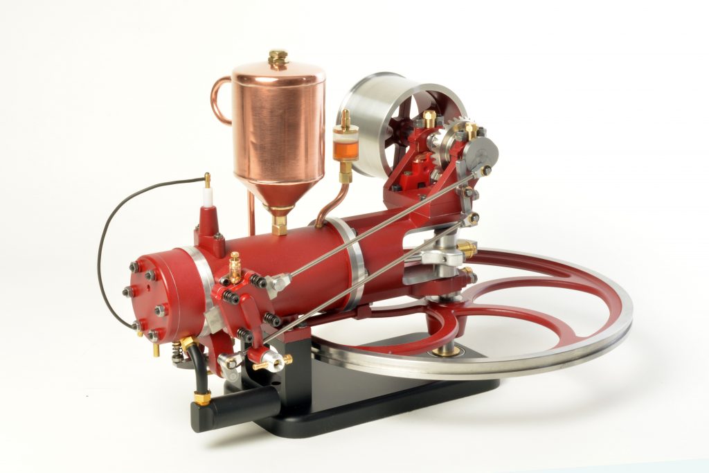
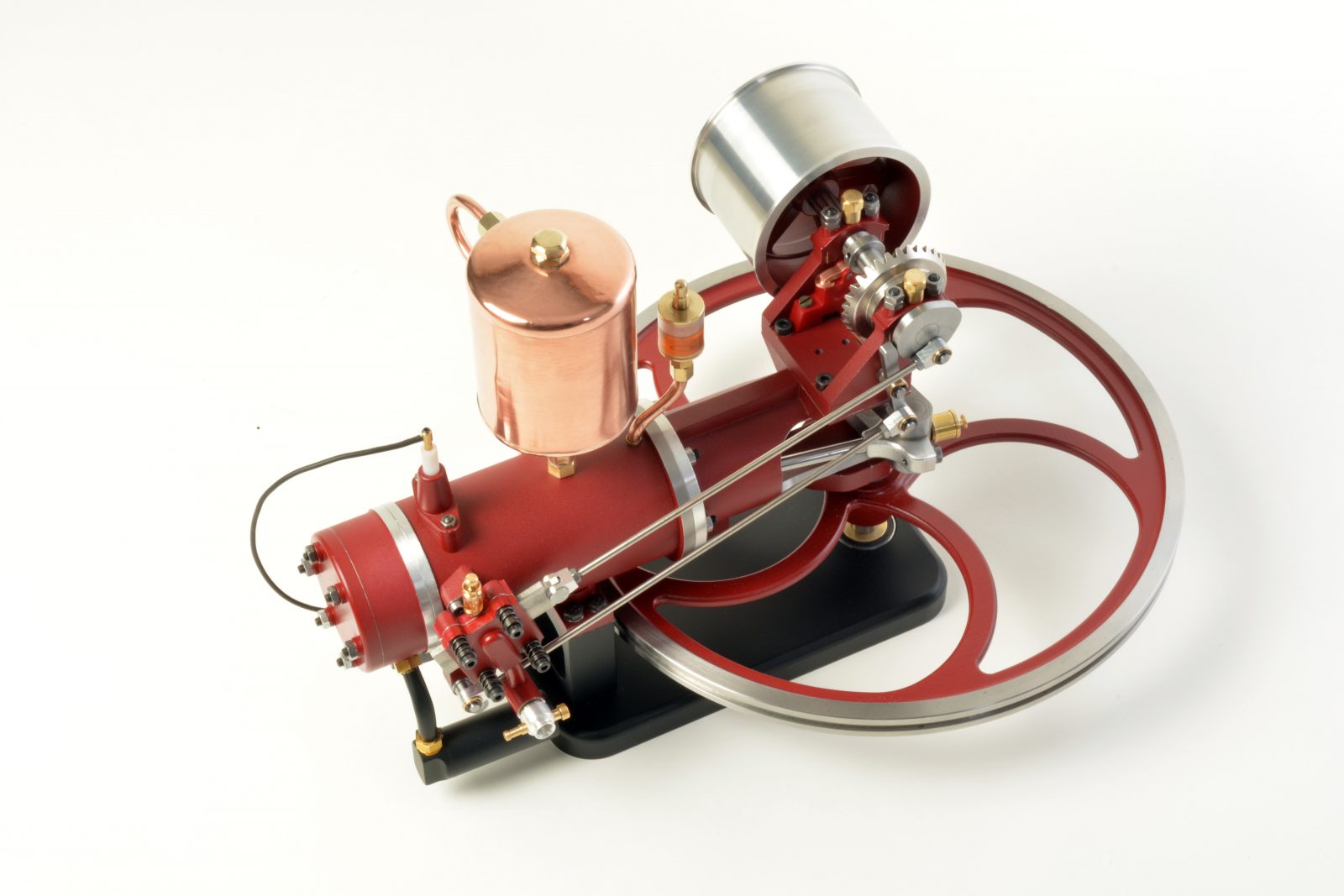
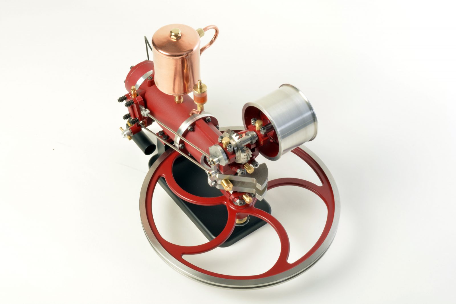
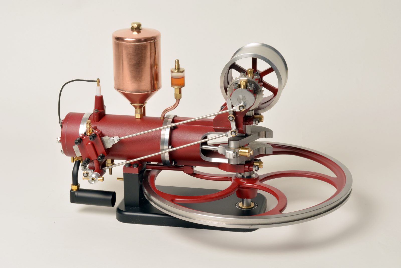
Pictures of the individual components
Benz engine from 1885
Carl Friedrich Benz (1844-1929) is considered one of the greatest inventors of all time. Among other things, he invented the carburettor, the differential, the Ackermann steering system and much more.
Historical background
The 4-stroke engine, however, was invented by Nicolaus August Otto (1832-1891), among others, so this engine has been officially called Otto engine in his honour since 1936.
Otto applied for two patents for his engine:
- Patent DE 532 A in 1877
- Patent DE 10 116 A in 1879
However, patent lawsuits in 1886 led to his patent from 1879 being revoked because the 4-stroke working sequence had already been described in a publication by the French engineer Alphonse Beau de Rochas in 1862.
However, before Carl Benz began developing combustion engines, he founded a mechanical workshop in Mannheim in 1871. And although the four-stroke engine was covered by Otto’s patent, Carl Benz developed and built a four-stroke engine around 1884 which could also be installed in vehicles, since the four-stroke engines built up to that time were mainly used as stationary engines and their weight of several tons made their use in vehicles impossible.
Conception of the original engine
Benz designed the engine as a horizontal 4-stroke with a large flywheel. The engine had a simple evaporative cooling system, a flat intake slide valve known from steam engines and already an exhaust valve, which was operated by a cam (which also controlled the intake slide valve) via a bumper and rocker arm. In addition, the engine already had an electric ignition invented by Benz.
The motor had a bore of 90 mm and a stroke of 150 mm. It produced 551 watts at a maximum speed of 400 revolutions per minute and was a lightweight of “only” 110 kilograms at that time.
Another special feature of his engine was that, unlike the common gas engines, it was not supposed to burn gas but a liquid fuel, which was much more efficient. Thus Ligroin, a mixture of alcohol and petrol, was used, which at that time, however, could only be bought in pharmacies. Accordingly, Benz also invented the (surface) carburettor necessary for a liquid fuel.
Der Benz-Motorwagen
At the same time as the engine, Carl Benz also developed and built his famous three-wheeled motor vehicle, in which he installed his engine. Test drives were carried out in his own factory yard and in October 1885 “secretly” in night-time Mannheim.
And Benz was lucky: Since, as mentioned, Nicolaus August Otto’s 4-stroke patent expired in 1886, Carl Benz was able to apply for a patent for his motor car on 29.01.1886 as a “first automobile equipped with an Otto engine” and the patent number DRP 37435 with the designation “Benz Patent Motor Car Number 1”.

An improved successor model, the “Benz Patent Motor Car Number 3”, achieved fame when Carl Benz’s wife, Bertha, and their sons Eugen and Richard drove from Mannheim to Pforzheim, 106 kilometers away, to visit their parents in the early morning of August 1888 without their husband’s knowledge.
However, the population reacted rather mockingly to the rattling and stinking vehicle during test drives and a high official is said to have made the following statement during this time: The automobile will never prevail over the horse-drawn carriage…
The replica
Research work in advance
First considerations concerned the scale for the engine. Since I probably wanted to produce the three-wheeled motor car after the construction of the engine, a scale of 1:3 seemed to me to be suitable, thus the engine has a capacity of 35.3 ccm with a 30mm bore and 50mm stroke.
My request to Mercedes Benz whether it might be possible to obtain drawing copies of the original engine was unfortunately rejected on the following grounds: “If I were to produce the vehicle with engine commercially in a required quantity, I could obtain a corresponding licence”…
On the Internet there is an abundance of photos of the vehicle, but these show almost exclusively, with a few exceptions, replicas.
So I studied the original photographs and the photos of the replicas and calculated at least the outer dimensions of the engine in the original to adjust them to the appropriate scale.
Further technical data of engine I also found at internet and corresponding literature.
The conception of the replica
Scale enthusiasts may forgive me, but I have made a few changes compared to the original engine, which I will discuss in the following text. First of all, I would like to mention that my engine runs on a methanol/oil mixture and glow ignition. But I have already installed a simple mechanical breaker, which is driven by the transverse shaft via a cam, just like the original, so I can later change the engine to spark ignition.
The original engine had a very low compression ratio of about 2.5:1, because at that time people did not dare to compress more. At that time there was also a lack of precise knowledge about the combustion process, combustion chambers and control times, and the materials to be used, e.g. the piston and cylinder, were still in the experimental stage.
Since my engine should run as cool as possible and at a low speed, I also chose a low compression, because the higher the compression (up to the knock limit of the fuel), the higher the braking torque on the crankshaft during the compression stroke and the higher the combustion temperature of the engine during the working stroke. However, I doubled the value compared to the original engine to a compression ratio of about 5.2:1, which is still a very low value compared to today’s usual compression ratio of about 10:1 for 4-stroke (gasoline) engines.
The original engine had, as already mentioned, a simple evaporative cooling system, which required about 10 times more water than fuel during the mentioned historical journey of Bertha Benz and her sons.
I kept the water cooling for the model engine, but chose a forced circulation cooling with a small pump, whereby heat is radiated to the surrounding air via the large surface of the copper cooling water tank sitting on top of the engine.
The correctness of this consideration was confirmed during the later test runs of the engine, whereby the cooling water (with a small addition of glycol for aluminium engines) only heated up to about 65 degrees.
The production of the motor
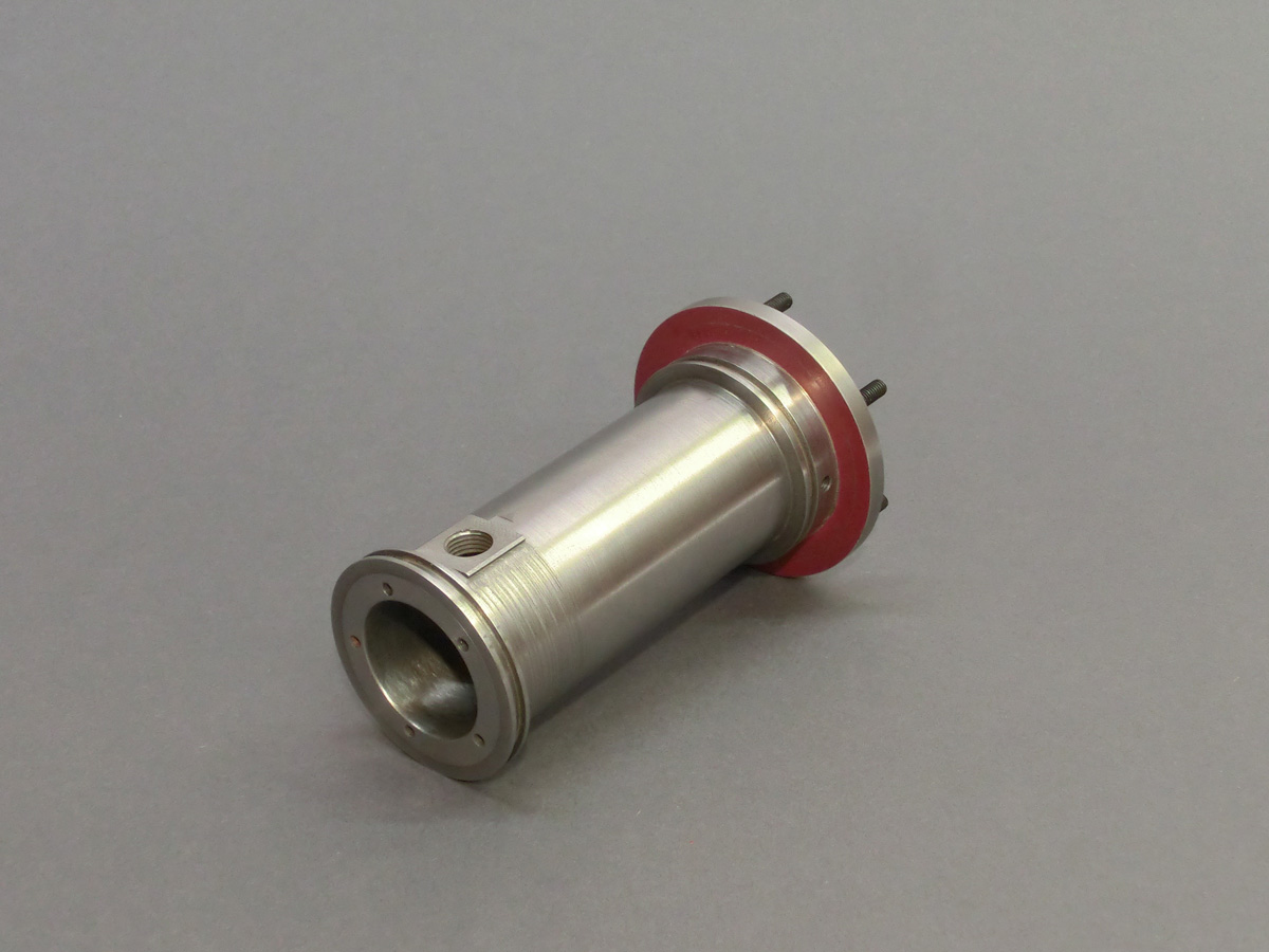
I started the construction of the engine by manufacturing the liner, which is made of grey cast iron GG-25 and has a honed bearing surface for the piston inside. This component is already a bit complicated, because besides the flanges on both sides to hold and seal the aluminium cooling water jacket, it also got a flat milled surface with a continuous M10x1 thread.
The inlet port for the flat slide valve was later screwed into this thread during the final assembly of the engine using a specially manufactured tool. The difficulty here was that the thread and the hole in the cooling water jacket had to be in alignment. The sealing to the surface of the liner and to the cooling water jacket is provided by an O-ring made of Viton. This material is suitable for higher temperatures.
The inlet port for the flat slide valve was later screwed into this thread during the final assembly of the engine using a specially manufactured tool. The difficulty here was that the thread and the hole in the cooling system had a 6mm hole on the inside and is controlled on the outside by the flat slide valve, which opens and closes the 6mm hole during the intake stroke after the control times of the engine.
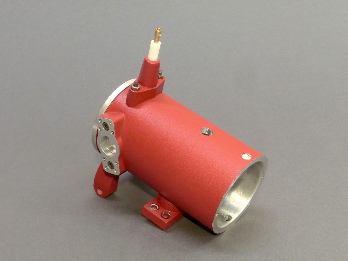
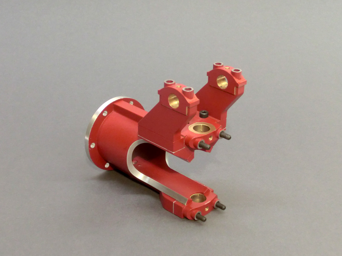
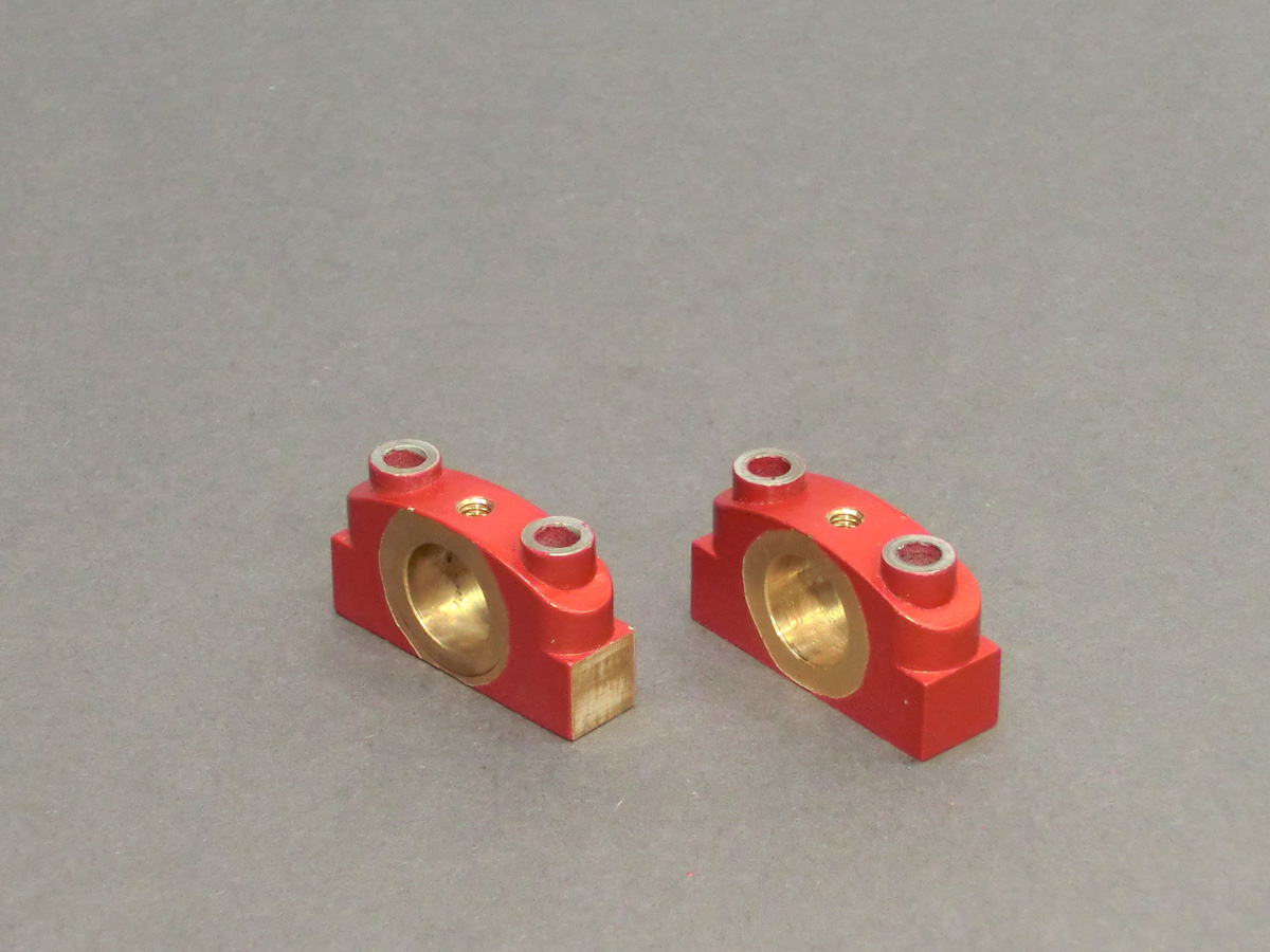
The front part of the engine consists of several individual parts that are bolted together. Some of the bolted parts were filled with a small radius before painting, which gives the impression of a cast part.
In the front part of the engine there are two slide bearings each made of gunmetal RG-7 to support the crankshaft and the cross shaft.
On one side of the transverse shaft is the cam, which moves the intake slide via a crank and simultaneously actuates the exhaust valve via a rocker arm.
On the opposite side sits the large belt wheel, which later in the vehicle via a flat belt provides the drive for the vehicle.
The transverse shaft is driven by a bevel gear set from the crankshaft with a transmission ratio of 2:1.
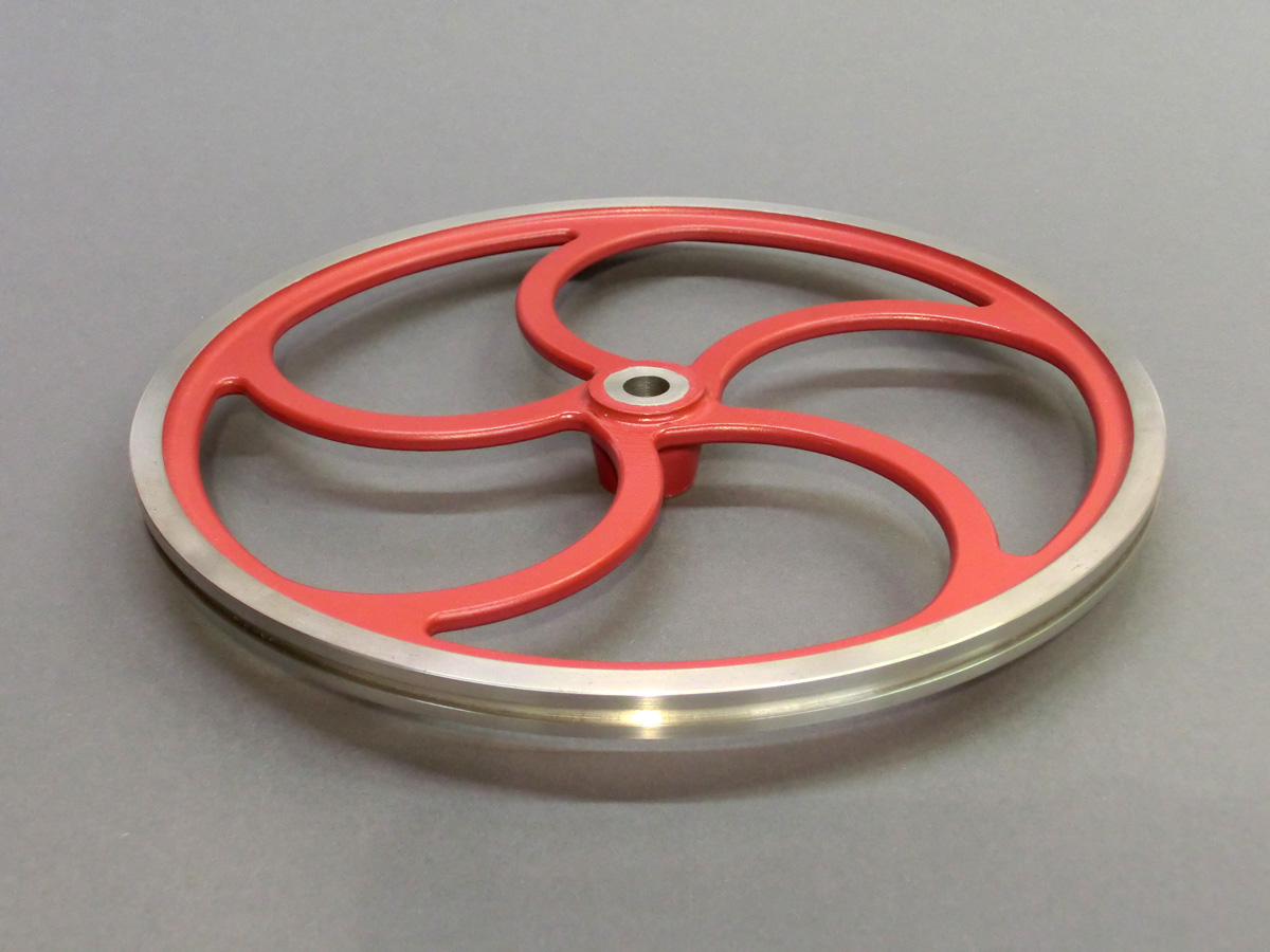
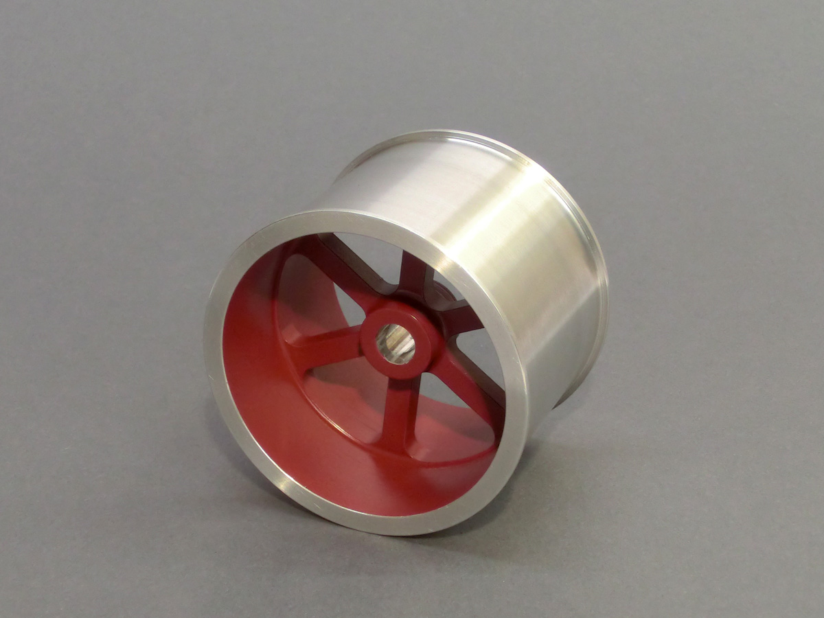
Another component that I do not want to leave unmentioned in my report is the large flywheel. It has a diameter of 262mm and was machined from a solid disc of steel C-45. Although I was able to manufacture it on a small industrial lathe (centre distance 650mm, centre height 160mm), machining was often difficult and my lathe reached its limits.
The milling of the gaps for the 5 spokes was done by my small CNC milling machine. But I had to produce fixtures for clamping, both for turning and later for milling, in order to be able to work the big flywheel safely.
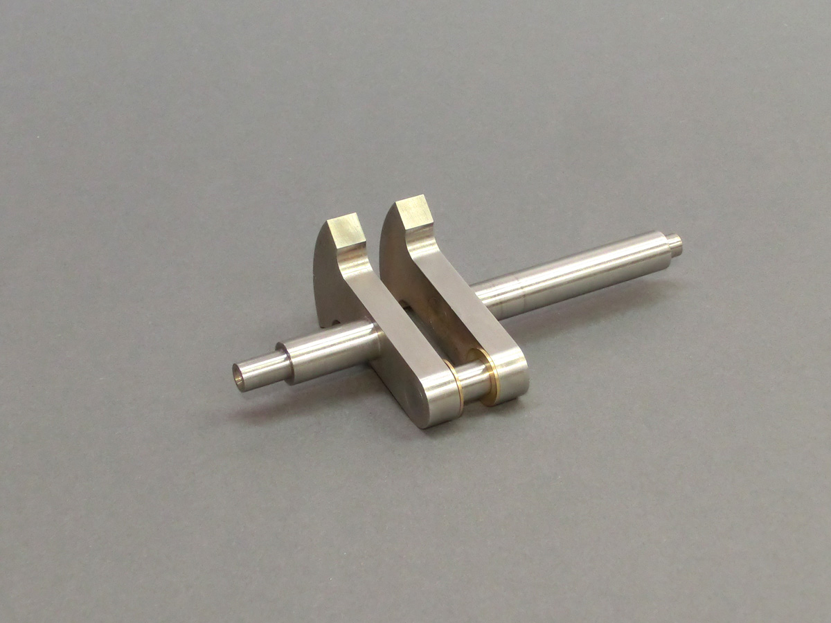
The crankshaft consists of 5 individual parts. The crankpin and the two main bearing pins I put into the crank webs with a very small press fit and Loctite 648. The diameter of the two main bearing journals was about 0,5mm after joining. To turn them to the exact diameter, I fixed a bolt opposite the crank pin between the crank webs, which was made to the exact length and fitted without play between the crank webs.
Now the two main bearing journals could be turned to finished size between the centres.
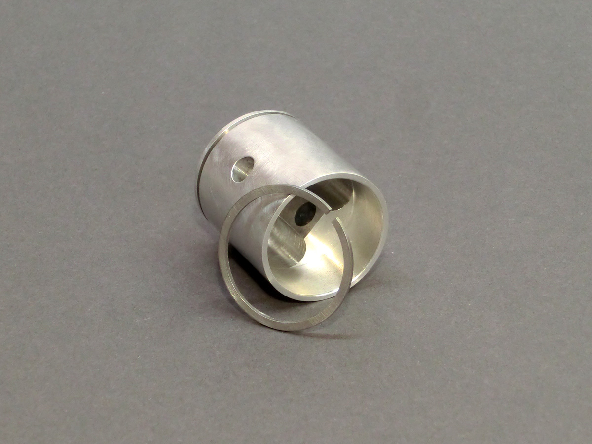
As material for the piston I chose the alloy AlCuMgPb. This material is easy to machine and has good sliding properties in the grey cast iron liner (GG-25). I made the piston ring from the free-cutting steel 9SMnPb28K. This material combination has proved to be very successful.
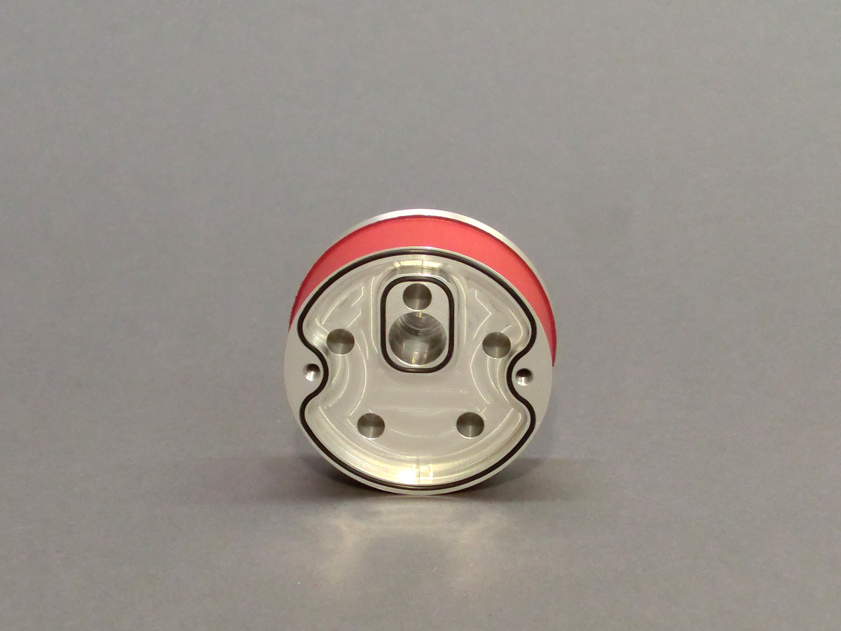
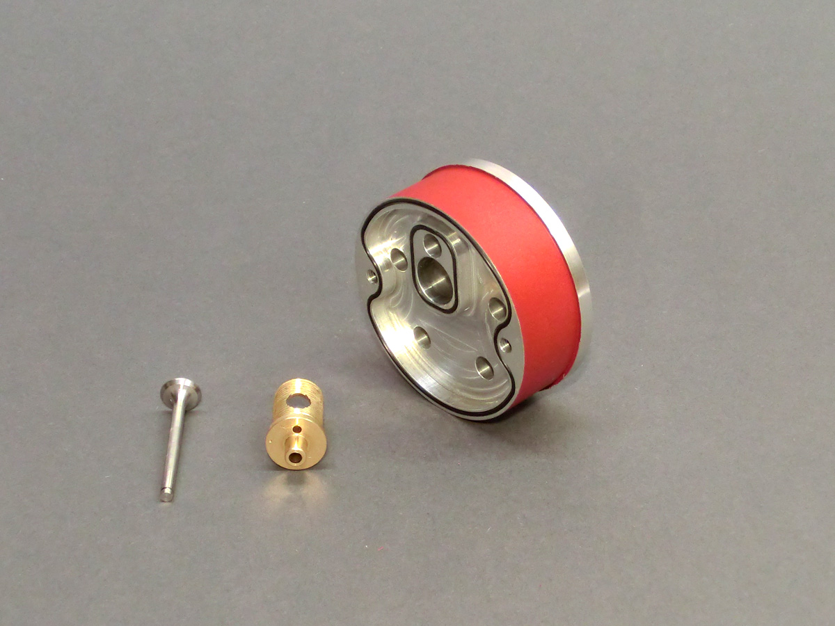
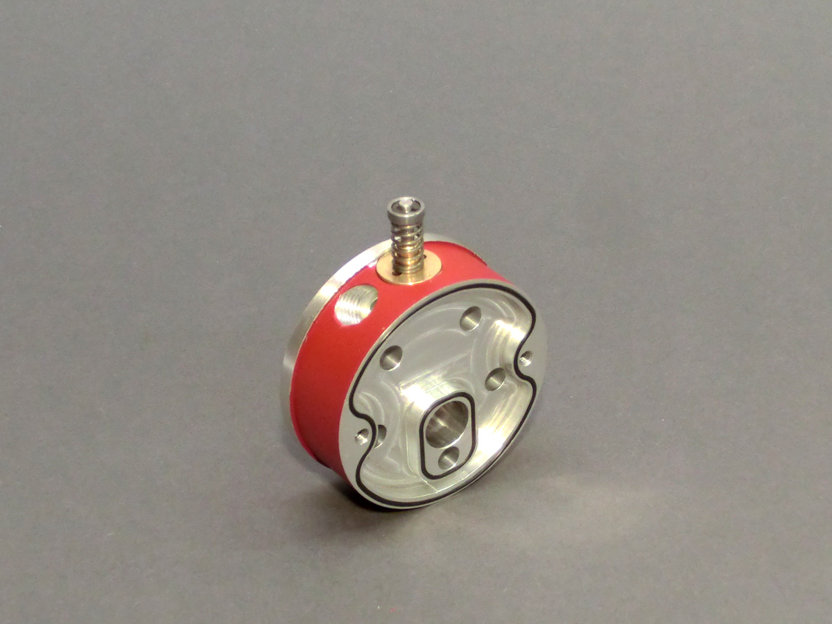
Another demanding component is the cylinder head, which, like the cylinder, is water-cooled. It is made of the same material as the piston because of its good machinability and has a rear cover which, like the countersink for the glow plug, is sealed with an O-ring.
The valve guide with the 45 degree seat for the exhaust valve consists of one part. It is made of gunmetal RG-7 and has a continuous M12X1 thread on the outside. It was later screwed into the corresponding internal thread of the cylinder head with a special tool during final assembly.
The valve can later open into a groove-shaped recess in the cylinder head during engine operation.
It was difficult to drill the inclined outlet channel into the hollow area of the valve guide.
The procedure was as follows:
- die Ventilführung (ohne eingesetztes Ventil) in den Zylinderkopf schrauben (mit Spezialwerkzeug festziehen)
- drill the outlet channel into the cavity of the valve guide, the
- screwing the valve guide back out of the cylinder head
- deburr everything carefully.
Now the exhaust valve could finally be placed in the valve guide.
During the subsequent final assembly in the cylinder head, a sealant (Hylomar) was used, which was applied to the thread and the outer flange.
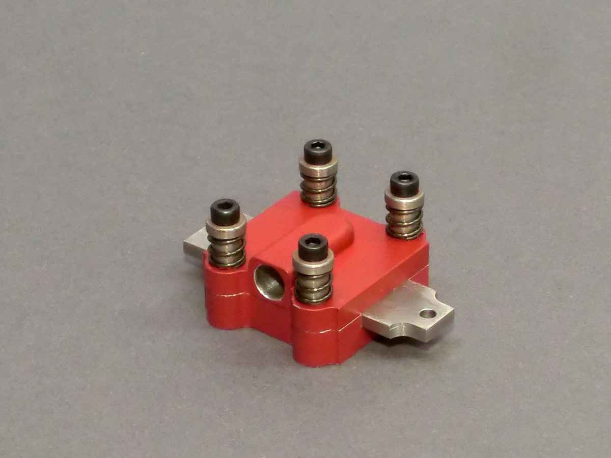
As already mentioned, the inlet control is done by a flat slide valve. I made it out of stainless steel and it slides directly in the aluminium housing. The whole thing is closed with a lid, also made of aluminium. In this cover is also the inlet channel hole, which is controlled by the slider.
In the original engines of that time, four springs usually pressed the cover onto the slide for sealing purposes.
However, I chose a different way for my model motor: The groove depth in the slider housing is exactly adapted to the thickness of the slider, so that it slides in the housing with a minimum of play.
Lubrication is provided exclusively by the oil content of the fuel. The advantage here is that a normal model engine fuel is used. This has a high oil content of approx. 20%.
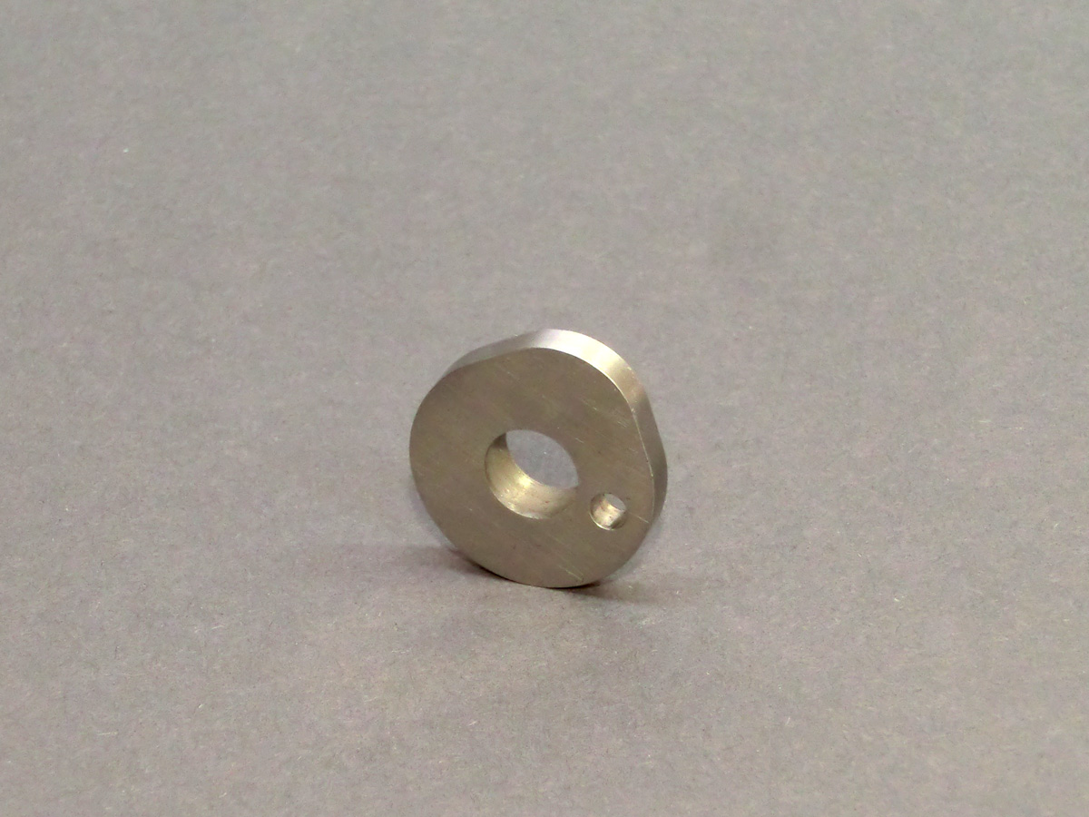
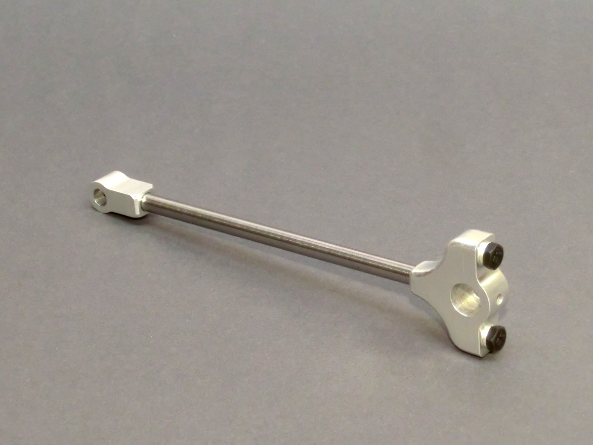
The connecting rod consists of three parts:
- Silver steel rod
- Piston
- Aluminium crankshaft bearing
The crankshaft bearing has two parts for assembly reasons. When assembling the two bearings I went a new way for me: Since the connecting rod of combustion engines is generally loaded almost exclusively in compression (during compression, the working stroke and during ejection) and only during the intake stroke is there a minimal tension load, I glued the lower and upper bearing to the connecting rod with Loctite 648. Since the cylinder is open at the bottom, the bearing for the piston is air-cooled in a certain way and the crankshaft bearing is air-cooled by the rotation anyway.
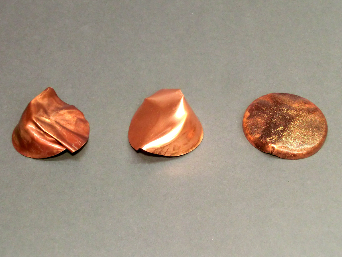
The cooling water tank is made of 0.3mm thick copper plate. Since the cover of the tank has a curved shape with a collar in the original, I made a pressing tool for its production and after some tests I could produce a usable copy.
As the cooling water does not become very hot during operation, as mentioned, the individual sheet metal blanks did not have to be brazed. I used a normal soft solder, which resulted in a usable container even after many attempts.
Summary
The engine has been running on the test bench for some time now. It spins nice and slow in idle speed at about 600-700 rpm and its distinctive rattling sound reminds very much of the original.
It was a very interesting project for me, which lasted for many months and also raised some odd problems, but the beautiful appearance of the engine and the distinctive running noise makes you forget all the work.
Amazing work, beautiful engine,
I would like to buy a plan to build it.
I’m glad you like the engine. Unfortunately, there are no blueprints for this engine.
Greeting,
Martin